Contents |
1. IntroductionThis page discusses the concepts behind the design of software life cycle models (SLCMs). It provides you with the basic building blocks of a model and gives examples of their use. Armed with this information you can:
|
A software life cycle model (SLCM) is a representation of the major components of software development work and their interrelationships in a graphical framework that can be easily understood and communicated. Just as the WBS partitions the deliverable into its component parts so the SLCM apportions the work to be done into manageable work units.
You must have a defined SLCM for your project to:
A SLCM achieves this by:
In planning software development you need to consider the complete exercise as a process. To effectively manage it you need to break it up into component subprocesses. Figure 107.1. presents the 3 main classes of software development process and gives examples of the members of each class.
Figure 107.1. Software life cycle process classifications.
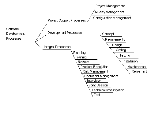
Project Support Processes are involved with the management of the software development exercise. They are performed throughout the life of the project.
Development Processes embody all work that directly contributes to the development of the project deliverable. They are typically interdependent.
Integral processes are common processes that are performed in the context of more than one development activity. For example, the review process is performed in the context of requirements definition, design and coding.
Processes are described in terms of a series of work units. Work units are logically related chunks of work. For example, all preliminary design effort is naturally chunked together. Figure 107.2 describes the components of a work unit.
Figure 107.2. Components of a work unit.
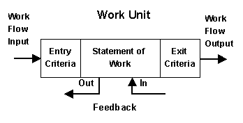
A work unit is described in terms of:
Work Flow Input/Output. Work flows are the work products that flow from one work unit to the next. For example, in figure 107.1 the design specification flows from the output of the design work unit to the input of the code work unit. Work flows are the deliverables from the work unit. All work units must have a deliverable. The life cycle model should provide detailed descriptions of the format and content of all deliverables.
Entry criteria are the conditions that must exist before a work unit can commence.
Statement of work (SOW). The SOW describes the work to be performed on the work flow inputs to create the outputs.
Exit criteria. The conditions that must exist for the work to be deemed complete.
Table 107.1. Examples of entry and exit criteria and statements of work.
| Entry Criteria | Statement of Work | Exit Criteria |
|
|
|
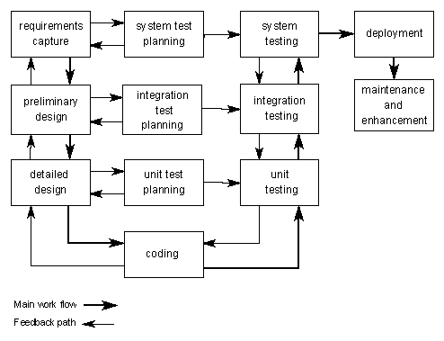
Feedback paths are the paths by which work performed in one work unit impacts work either in progress of completed in a preceding work unit.
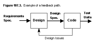
For example the model depicted in figure 107.3 allows for the
common situation where the act of coding often uncovers
inconsistencies and omissions in the design. The issues raised by
programmers then require rework of the baselined design document.
Defining feedback paths provides a mechanism for iterative development of work products. That is, it allows for the real world fact that specifications and code are seldom complete and correct at their first approval point. The feedback path allows for planning, quantification and control of the rework effort.
Implementing feedback paths on your project requires the following procedures:
Figure 107.4 provides an example of a life cycle model constructed by sequencing work units.
Figure 107.4. Life cycle model.

In figure 107.4 examples of work flows are requirements specification and design specification. The work units are Design, Code and Test and the feedback paths carry requirements, design and coding issues.
Note that the arrows in a life cycle model do not signify precedence. For example, in figure 107.4 all design does not have to be complete for coding to commence. Design may be continuing while some unrelated elements of the system are being coded.
A primary purpose of the life cycle model is to communicate the work to be done among human beings. Research has shown that humans have a problem dealing with more than 9 chunks of information at one time (refer to George A. Miller's concept of a "chunking limit"). To guarantee comprehension, a single life cycle model should therefore not have more that 9 work units. Clearly this would not be enough to describe even the simplest projects.
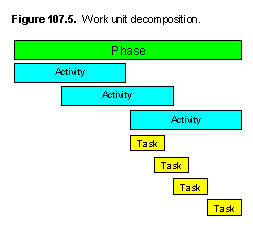 Work
Unit Leveling
The solution is to decompose large work units with a set of
levels with each level providing more detail about the level
above it. Figure 107.5 depicts 3 levels of decomposition.
Note that phases, activities and tasks are all types of work unit. You can therefore describe them all in terms of entry criteria, statement of work and exit criteria.
Figure 107.6 provides a phase level life cycle model for a software development project.
Figure 107.6. A generic project model.
[19] IEEE Standard for Developing Software Life Cycle Processes.
[20] Controlling Software Projects, Tom DeMarco. Refer chapter 13.
[2] Managing the Software Process, Watts Humphrey. Refer chapter 13.
[21] ISO/IEC 12207:1995 Information technology -- Software life cycle processes
Software Engineering Web
Copyright ã 1997 Chambers & Associates Pty Ltd
Module: 107 v1.0 c_pmodel.htm
Updated: July 02, 2006